Thermal pulsation systems have become a widely used technical solution for treating evaporative dry eye associated with meibomian gland dysfunction. From an engineering standpoint, these devices are not simply eyelid warmers but tightly controlled thermal-mechanical systems operating within narrow safety margins. In this article, I look at how modern thermal pulsation equipment is actually built, which design decisions matter in real clinical use, and where engineers have had to compromise between effectiveness, safety, and long-term reliability.
Why Thermal Pulsation Became a Practical Engineering Solution for Dry Eye
When I look at dry eye disease from an engineering perspective, the key issue is not inflammation or tear volume but heat transfer and flow mechanics. Evaporative dry eye associated with meibomian gland dysfunction (MGD) is, at its core, a problem of lipid viscosity and obstruction. Normal meibum begins to soften at temperatures above roughly 40–41 °C, while pathological meibum often requires 42–45 °C to achieve meaningful viscosity reduction. This temperature gap is precisely where home remedies and early clinical approaches fail.
Standard warm compresses typically deliver surface eyelid temperatures in the range of 34–38 °C, and only for a few minutes before cooling. From an engineering standpoint, this is insufficient both in magnitude and stability. Heat loss through skin, orbicularis muscle, and blinking introduces large variability. Thermal pulsation systems exist because engineers were asked to raise tissue temperature into a narrow therapeutic window and hold it there safely, repeatedly, and predictably.
Vision Support: Quality AREDS 2 Formula eye vitamins can be found on Amazon.
Temperature Control: Numbers That Matter
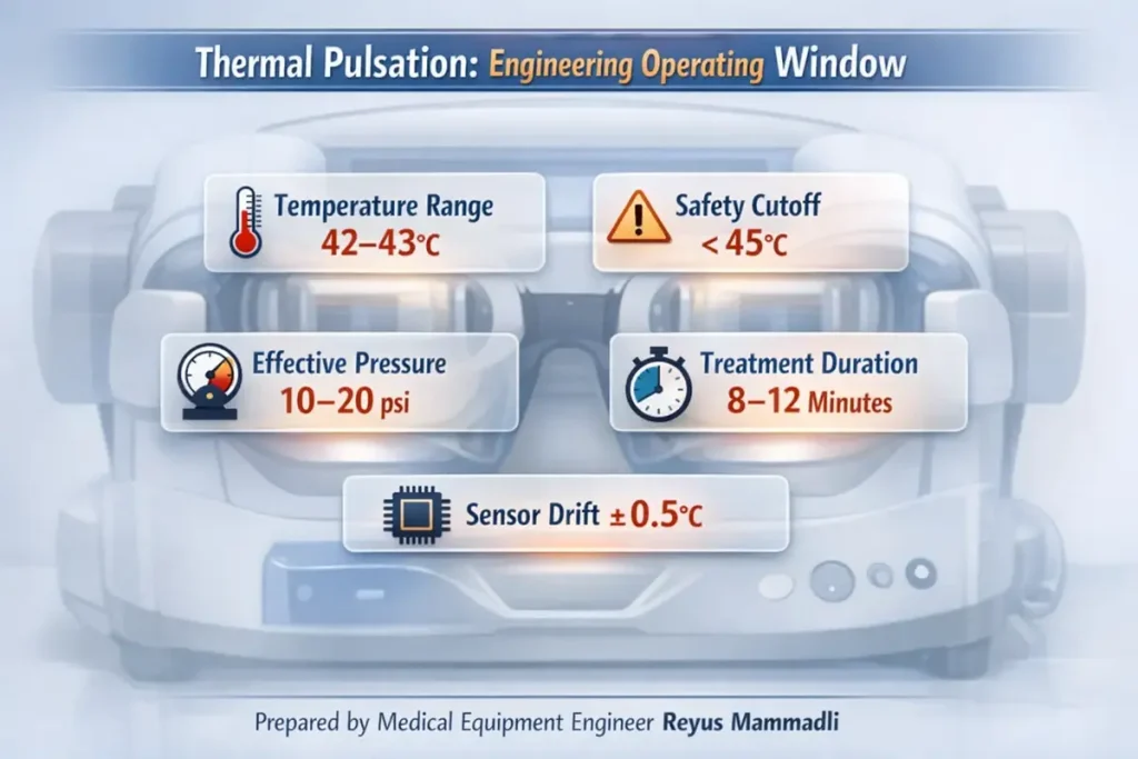
Modern thermal pulsation platforms typically target inner eyelid temperatures around 42–43 °C, with safety cutoffs below 45 °C. The difference between these numbers may seem small, but from an engineering perspective it is critical. Protein denaturation and epithelial injury risk increase rapidly above this range, while meibum liquefaction drops sharply below it.
What I pay attention to is not the nominal temperature, but:
- Sensor location (tissue-adjacent vs. heater-adjacent)
- Control accuracy (often ±0.5–1.0 °C in better systems)
- Thermal lag during blinking or pressure cycles
Systems that infer temperature indirectly tend to run cooler for safety, often sacrificing effectiveness. This is a deliberate engineering compromise, but one that shows up clinically as variable outcomes.
Why Pressure Was Added to Heat
Heating alone does not evacuate obstructed glands. Mechanical expression is required to overcome ductal resistance. Measurements of manual gland expression show forces ranging roughly from 5 to 30 psi, depending on obstruction severity and technique. The problem is not reaching these pressures—it is doing so uniformly and safely across the eyelid.
Thermal pulsation devices typically limit applied pressure to well below what can be generated manually, often in the range of 10–20 psi, delivered in pulses rather than static compression. From an engineering standpoint, pulsed pressure reduces peak stress on tissue while improving secretion mobilization. This is a classic mechanical trade-off: lower amplitude, higher repeatability.
Expert Choice: Recommended by eye care professionals for managing dry eyes, styes, and blepharitis, this Heated Eye Mask provides the consistent moist heat therapy endorsed by the American Academy of Ophthalmology. It’s an effective, reusable solution for soothing irritation and improving oil gland function. Available on Amazon.
Core Engineering Variables Across Systems
Even before comparing specific devices, the category can be described using a small set of measurable parameters:
| Engineering Parameter | Typical Range | Why It Matters (Engineer’s View) |
|---|---|---|
| Target temperature | 42–43 °C | Below this, meibum remains semi-solid; above this, tissue risk rises |
| Temperature accuracy | ±0.5–1.0 °C | Directly affects safety margins and consistency |
| Treatment duration | 8–12 minutes | Balances thermal diffusion with patient tolerance |
| Pressure range | ~10–20 psi | Sufficient for expression without structural trauma |
| Interface type | Single-use, polymer | Eliminates calibration drift and hygiene variables |
These numbers are not marketing claims; they are constraints imposed by tissue physics and materials science.
Single-Use Interfaces: An Engineering, Not Marketing, Choice
From a purely mechanical perspective, reusable patient interfaces are problematic. Polymers exposed to repeated heating cycles at >40 °C, combined with moisture and mechanical loading, undergo measurable changes in stiffness and thermal conductivity over time. Even small changes alter pressure distribution and heat transfer.
Single-use interfaces reset these variables for every treatment. As an engineer, I see this as a way to eliminate uncertainty rather than upsell consumables. The downside is obvious—operational cost—but the benefit is predictable performance without constant recalibration.
Specialized Care: For persistent itching or flaking, eye care specialists recommend targeted formulas like this BetterLids Eyelid Ointment . This preservative-free, dermatologist-tested oat complex is a top choice for soothing sensitive skin and managing symptoms of blepharitis. Available for easy ordering on Amazon.
Automation vs. Operator Control
Current systems fall into two main mechanical philosophies:
- Fully automated pneumatic systems, where pressure profiles are software-controlled and repeatable
- Operator-assisted systems, where temperature is stabilized but expression force is manually applied
Automated systems typically use miniature pumps, valves, and pressure sensors operating at relatively low duty cycles. This improves repeatability but introduces more components that can fail. Manual systems reduce mechanical complexity but reintroduce human variability. Neither approach is universally better; they simply distribute risk differently.
Temperature and Pressure Sensors: What Is Actually Used
One area where engineering details are usually hidden is sensing. Yet sensors largely define both safety and repeatability.
Temperature sensing in thermal pulsation systems is almost always based on contact thermistors or, less commonly, thin‑film RTDs. Infrared sensors were explored early on, but most manufacturers abandoned them because emissivity of moist ocular tissue is variable and calibration drift was unacceptable in a medical safety context.
In practice, the dominant solutions are:
| Sensor type | Typical specs | Why manufacturers choose it | Engineer’s comment |
|---|---|---|---|
| NTC thermistor (medical grade) | Accuracy ±0.2–0.5 °C, response <1 s | Low cost, fast response, small form factor | Excellent for closed-loop control, but aging and moisture ingress can shift calibration over years |
| Thin‑film RTD (Pt100 / Pt1000 class) | Accuracy ±0.1–0.3 °C, very stable | Long-term stability, predictable drift | More expensive and mechanically fragile; often avoided in disposable interfaces |
From what I see in teardown reports and service manuals, most systems rely on NTC thermistors sourced from established suppliers in Japan or Europe, integrated close to the tissue-contact surface. The expected electrical lifespan of these sensors is typically >100,000 hours, but mechanical and environmental stress, not electronics, define real-world limits.
The key engineering risk here is not sensor failure, but slow drift. A 0.5 °C shift over several years may remain invisible to the user yet meaningfully reduce treatment effectiveness or safety margin.
Pressure Sensing and Control
Pressure monitoring is usually achieved with MEMS-based piezoresistive pressure sensors, commonly rated for ranges up to 30–50 psi, even if the system only operates below ~20 psi. This overspecification is intentional: it improves linearity and reduces fatigue.
Typical characteristics include:
- Accuracy: ±1–2% full scale
- Response time: milliseconds, sufficient for pulsed profiles
- Operational life: tens of millions of cycles under benign conditions
These sensors are widely used across medical devices—from infusion pumps to respiratory systems—which speaks to their maturity. Failures I have encountered are rarely due to silicon degradation; more often they stem from tubing leaks, condensation, or connector wear.
Why Some Sensor Approaches Were Abandoned
Earlier prototypes and niche devices experimented with:
- Non-contact IR temperature sensing
- Reusable pressure bladders with embedded sensors
Both approaches struggled with consistency. IR systems required frequent recalibration due to surface reflectivity changes. Embedded reusable sensors suffered from mechanical fatigue and cleaning-induced drift. From an engineering reliability standpoint, these designs were elegant but unforgiving.
The current trend toward sensor-adjacent single-use interfaces is a response to these lessons. It limits lifespan concerns to one treatment and shifts long-term reliability to the base unit, where conditions are more controlled.
Reliability and Degradation Over Time
Sensor degradation is gradual, not catastrophic. This is precisely what makes it dangerous. A system can remain functional while slowly drifting out of its optimal operating window.
Designs that either reset sensing components each treatment or maintain wide safety margins tolerate this reality better. Systems that depend on long-term absolute accuracy without enforced calibration rely heavily on user discipline, which is rarely perfect in busy clinics.
Market Survival as an Engineering Outcome
From what I see in U.S. clinics, devices that survive are not necessarily the most advanced, but the most forgiving. Platforms built around standard resistive heaters, mature thermistors, and widely used MEMS pressure sensors are easier to service and support over a 5–10 year lifespan.
Exotic sensing approaches may promise higher precision, but unless they tolerate moisture, heat cycling, and imperfect handling, they struggle outside controlled conditions.
Preparing for Direct System Comparison
With these baseline numbers and component-level choices in mind, it becomes easier to evaluate individual platforms. In the next section, I will compare several widely used modern thermal pulsation systems and examine how their specific engineering decisions—sensor placement, control algorithms, and interface design—affect real-world performance, reliability, and workflow integration.
The goal is not to crown a winner, but to understand how design decisions translate into daily clinical reality.
Comparing Modern Thermal Pulsation Systems: Engineering Choices in Real Devices
At this point, the physics and constraints are clear. Now the interesting part begins: how different manufacturers chose to solve the same thermal‑mechanical problem. In this section, I focus on three widely used, modern thermal pulsation platforms present in U.S. clinics today. I am deliberately not ranking them by brand perception, but by engineering architecture, controllability, and long‑term behavior.
The systems discussed here represent three distinct design philosophies:
- a fully automated, closed pneumatic system
- a clinician‑guided thermal expression system
- a simplified thermal stimulation platform
Systems Included in This Comparison
The devices I am referencing are:
- LipiFlow® Thermal Pulsation System
- iLux® MGD Thermal Pulsation System
- MiBoFlo® Thermal Therapy System
They are all FDA‑cleared, commercially active, and supported in the U.S. market. More importantly, they differ enough technically to make comparison meaningful.
High‑Level Technical Comparison
Before diving into subsystems, it helps to put their core parameters side by side.
| Parameter | LipiFlow | iLux | MiBoFlo | Engineer’s Interpretation |
|---|---|---|---|---|
| Heat delivery location | Inner eyelid (palpebral) | Inner eyelid | External lid surface | Proximity to glands directly affects thermal efficiency |
| Target temperature | ~42.5 °C (fixed) | ~42–43 °C (adjustable) | ~42 °C (external) | Internal heating requires tighter control, but works faster |
| Temperature control | Closed‑loop, automated | Closed‑loop, operator‑adjusted | Timer‑based | Automation reduces variability but adds complexity |
| Pressure mechanism | Pneumatic pulsation | Manual expression | None / vibration only | Pressure is decisive for severe obstruction |
| Treatment duration | ~12 minutes | Variable (≈8–12 min) | ≈10 minutes | Duration compensates for weaker heat or pressure |
| Patient interface | Single‑use, integrated sensors | Single‑use applicator | Reusable probe | Interface choice defines consistency and cost |
These numbers already explain why clinical preferences diverge.
LipiFlow: Fully Automated Thermal–Pneumatic Architecture
LipiFlow is the most mechanically complex system of the three. From an engineering perspective, it behaves like a self‑contained treatment robot. Heat is applied directly to the inner eyelid while pneumatic pulses evacuate glands from the outside.
Thermal Control
The system maintains a narrow thermal window around 42.5 °C using internal thermistors placed close to the tissue interface. The user cannot change this value, which is a deliberate safety choice. As an engineer, I see this as a conservative but robust design: fewer adjustable parameters mean fewer misuse scenarios.
Pressure Delivery
Pressure is delivered through a controlled pneumatic sequence. Typical peak pressures remain below 20 psi, applied cyclically rather than statically. This reduces ischemic risk while still mobilizing viscous meibum. The trade‑off is mechanical complexity—pumps, valves, and tubing must all remain leak‑free.
Strengths and Weaknesses
- Strengths: high repeatability, minimal operator dependence, strong clinical consistency
- Weaknesses: high capital cost, reliance on single‑use assemblies, more service‑sensitive architecture
In busy practices, its predictability is often worth the complexity.
iLux: Stabilized Heat with Human‑Controlled Expression
iLux takes a different approach. It stabilizes temperature electronically but leaves pressure generation largely to the clinician.
Thermal System
iLux maintains treatment temperatures in the low‑40 °C range, but allows the operator to modulate contact and duration. From an engineering standpoint, this introduces controlled variability. The system compensates by providing real‑time visualization of gland expression, which partially closes the feedback loop.
Mechanical Expression
Pressure is applied manually through the device. Measured forces can vary widely depending on clinician technique. This reduces internal mechanical complexity but shifts responsibility to training and experience. Engineers would describe this as human‑in‑the‑loop control.
Strengths and Weaknesses
- Strengths: portability, lower system complexity, visual feedback
- Weaknesses: operator‑dependent outcomes, harder to standardize across users
This platform works best where clinicians are highly engaged in the procedure.
MiBoFlo: Thermal Stimulation with Minimal Compression
MiBoFlo represents the simplest architecture. Heat is applied externally, often combined with vibration or massage.
Thermal Characteristics
Because heating is external, effective gland temperatures rise more slowly. In practice, this is compensated with longer treatment times. From a heat‑transfer perspective, this is less efficient but mechanically safer.
Mechanical Simplicity
There is no active pressure system. This dramatically improves reliability and lowers cost but limits effectiveness in advanced obstruction. Engineers often describe such systems as low‑risk, low‑force solutions.
Strengths and Weaknesses
- Strengths: simplicity, low maintenance, minimal consumables
- Weaknesses: reduced efficacy for severe MGD, greater dependence on adjunct therapies
What These Differences Mean in Practice
From an engineering viewpoint, these platforms are not competing on the same axis. LipiFlow prioritizes automation and repeatability. iLux prioritizes clinician control and flexibility. MiBoFlo prioritizes simplicity and durability.
None of these choices are wrong. They simply align with different assumptions about clinic workflow, patient mix, and tolerance for complexity.
Engineering Trade‑Offs Clinics Often Underestimate
Two issues consistently surface during long‑term use:
- Consumable dependency: Single‑use interfaces stabilize performance but lock clinics into supply chains.
- Calibration discipline: Systems that rely on absolute sensor accuracy assume regular maintenance, which is not always realistic.
These factors often matter more over five years than initial purchase price.
Transition Toward Operational Reality
So far, I have focused on how these systems are built and controlled. In the final section, I will step away from specifications and look at what happens after hundreds or thousands of treatments: wear, service patterns, real operating costs, and where future engineering improvements are most likely to appear.
That is where theoretical design meets clinical reality.
What Happens After Installation: Long-Term Operation and Engineering Reality
Up to this point, I have discussed how thermal pulsation systems are designed and how they differ architecturally. The final and often underestimated phase begins after installation. From an engineering standpoint, this is where theoretical performance meets human behavior, service logistics, and component aging.
In U.S. clinics, these systems are typically expected to operate for 5–10 years, delivering anywhere from 1,000 to 5,000 treatments over their lifetime. Whether they remain predictable over that span depends less on headline specifications and more on how well the system tolerates imperfect conditions.
Wear Mechanisms That Actually Matter
Thermal Cycling and Materials Fatigue
Most core components—heaters, polymers, seals—experience repeated cycling between room temperature and >42 °C. Over thousands of cycles, this leads to:
- gradual stiffening of polymers
- changes in thermal conductivity
- micro-leaks in pneumatic pathways
From an engineering perspective, this is why systems relying heavily on single-use patient interfaces age more gracefully. The most stressed materials are discarded after each treatment, while the base unit operates in a relatively stable environment.
Pneumatics: Small Leaks, Big Consequences
In automated systems, pneumatic integrity is critical. Even a minor pressure leak—on the order of 1–2 psi loss—may not trigger an alarm but can significantly reduce gland expression efficiency.
In practice, the weakest points are:
- flexible tubing
- quick-connect fittings
- internal valves exposed to moisture
Clinics rarely measure delivered pressure directly, so gradual degradation often goes unnoticed unless outcomes decline.
Calibration and Maintenance: The Human Factor
Most manufacturers recommend periodic inspection or calibration at intervals ranging from 12 to 24 months. From an engineering risk perspective, the problem is not the interval—it is compliance.
Systems that:
- rely on absolute sensor accuracy, and
- lack self-diagnostic drift detection
are more vulnerable in busy practices. Designs with conservative control margins or consumable-based sensing tolerate skipped maintenance better. This difference becomes evident after several years, not during the first months of use.
Service and Technical Support in the U.S.
Support infrastructure is rarely discussed in technical literature, but it has real engineering implications.
Large Installed-Base Platforms
Systems with the largest U.S. footprint typically maintain regional service hubs rather than local offices. In practice, this means:
- service coverage across most major metropolitan areas
- typical on-site response times of 2–5 business days for non-critical issues
- expedited support (24–48 hours) available under premium service contracts
Replacement of base units, when required, is often handled through advance exchange rather than field repair—an approach that minimizes downtime but increases logistics cost.
Smaller or Simpler Platforms
Simpler systems with fewer moving parts tend to rely on:
- remote diagnostics
- shipment-based repairs
- fewer field engineers, often covering multiple states
Response times of 5–10 business days are not unusual, but failure rates are generally lower due to reduced complexity. From an engineering viewpoint, this is a classic reliability-versus-support trade-off.
Real Operating Costs Beyond Purchase Price
Engineers often separate capital cost from operating cost, but clinics feel both.
Key contributors include:
- single-use components per treatment
- preventive maintenance contracts
- downtime risk during peak schedules
Over five years, consumables can exceed the original hardware price. Systems with higher per-treatment cost but lower variability may still be economically rational if they reduce retreatment or chair time.
Where the Technology Is Likely to Evolve
From what I see in current development trends, future improvements will focus less on higher temperatures or pressures and more on:
- better real-time feedback (flow visualization, pressure confirmation)
- smarter fault detection rather than tighter tolerances
- materials that tolerate moisture and heat without drifting
Incremental engineering improvements, not radical redesigns, are most likely to shape the next generation.
An Engineer’s Practical Advice When Choosing a System
For clinicians or administrators without deep engineering backgrounds, there are still concrete steps that reduce risk. These are questions I would ask myself—or encourage others to ask—before committing to a platform.
1. Ask How Temperature Is Measured
- Where is the sensor located relative to tissue?
- Is temperature measured directly or inferred?
If the answer is vague, that is a warning sign.
2. Understand Pressure Limits
- What is the maximum delivered pressure?
- Is it pulsed or static?
Well-designed systems can state these numbers clearly and explain why they were chosen.
3. Clarify Calibration and Maintenance
- How often is calibration recommended?
- What happens if it is skipped?
A system that remains safe and effective despite imperfect maintenance is usually better suited for real clinics.
4. Map the Support Network
- How many service engineers cover your state or region?
- What is the typical on-site response time?
Concrete answers—days, not promises—matter here.
5. Look at the Consumables Critically
- What parts are single-use and why?
- Are they mechanical, thermal, or sensing-critical?
Consumables that stabilize performance are justifiable; those that add no engineering value deserve scrutiny.
Thermal Pulsation Systems: Key Wear Mechanisms
This technical infographic highlights the main engineering stress points in thermal pulsation systems used for dry eye treatment, focusing on heat, pressure, materials, and sensing stability.
Thermal Cycling
Repeated heating above 42 °C accelerates polymer fatigue and seal aging after thousands of treatment cycles.
Pneumatic Micro-Leaks
Even minor pressure loss may not trigger alarms but can significantly reduce gland expression effectiveness.
Polymer Fatigue
Heat, moisture, and mechanical stress gradually change stiffness and thermal conductivity of interface materials.
Temperature Sensor Drift
Small sensor drift narrows the safety margin in systems operating within a tight therapeutic window.
Consumable Dependency
Disposable components stabilize performance but increase long-term operating costs and supply-chain reliance.
Closing Engineering Perspective
Thermal pulsation systems succeed not because they are sophisticated, but because they operate within tight physiological constraints using conservative engineering. The best designs are not those that push limits, but those that behave predictably after thousands of cycles, across many users, under less-than-ideal conditions.
From an engineer’s viewpoint, that predictability—not novelty—is what ultimately supports reliable clinical outcomes.
Engineering Perspective Disclaimer
The analysis and opinions expressed in this article reflect my personal perspective as a medical equipment engineer. They are based on professional experience, review of publicly available technical documentation, and general engineering principles applied to medical devices.
Different engineers, clinicians, or manufacturers may reasonably interpret the same systems differently or prioritize other design trade-offs. This article is not intended to replace manufacturer documentation, clinical guidelines, or regulatory instructions for use. Its purpose is to provide an engineering-oriented interpretation of how these systems are built, why certain design decisions were made, and where practical limitations may arise.
References
- Johnson & Johnson Vision — https://www.jnjvision.com/
- Alcon — https://www.alcon.com/
- TearScience (Thermal Pulsation Technology) — https://www.tearscience.com/
- Mibo Medical Group — https://www.mibomedicalgroup.com/
- U.S. Food and Drug Administration (Medical Device Databases) — https://www.fda.gov/
- American Academy of Ophthalmology — https://www.aao.org/
- PubMed (Biomedical and Engineering Literature) — https://pubmed.ncbi.nlm.nih.gov/
- IEEE (Sensors, Control Systems, Medical Device Engineering) — https://www.ieee.org/
- National Institutes of Health — https://www.nih.gov/