Modern ophthalmic clinics rarely question whether imaging of the anterior segment is necessary. The real question is different: which physical principle should you rely on when structural detail determines diagnosis, surgical planning, or long‑term follow‑up?
In this article, I analyze Ultrasound Biomicroscopy (UBM) and Anterior Segment Optical Coherence Tomography (AS‑OCT) strictly from an engineering standpoint. I will focus on signal physics, system architecture, measurable parameters, and operational constraints. My goal is not to declare a winner. My goal is to clarify where each technology reaches its physical limits — because those limits are what ultimately shape clinical value.
I write this as a medical equipment engineer with formal training in biotechnical systems. I am not approaching the subject from marketing or clinical enthusiasm, but from signal behavior, attenuation coefficients, mechanical tolerances, and reproducibility metrics.
Vision Support: Quality AREDS 2 Formula eye vitamins can be found on Amazon.
Physical Principles: Acoustic Reflection vs Optical Interference
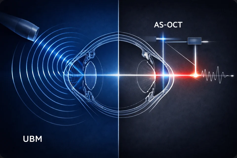
At the core, UBM and AS‑OCT differ not by brand or interface, but by physics.
UBM typically operates at 35–50 MHz, with some systems extending toward 70–80 MHz. At 50 MHz, the acoustic wavelength in soft tissue (assuming ~1540 m/s sound velocity) is approximately 30 µm. Axial resolution in pulse‑echo ultrasound is roughly half the spatial pulse length, which in high‑frequency ophthalmic probes translates into practical axial resolutions in the range of 25–50 µm, depending on bandwidth and damping characteristics.
However, attenuation increases rapidly with frequency. In soft tissue, attenuation is approximately 0.5–1.0 dB/cm/MHz. At 50 MHz, this means theoretical attenuation of 25–50 dB/cm. Even accounting for the very short path lengths in anterior segment imaging, this is why practical penetration depth is typically limited to 4–5 mm.
From an engineering standpoint, this is not a weakness. It is simply the predictable outcome of high‑frequency acoustic physics.
AS‑OCT, by contrast, relies on near‑infrared light, typically centered at 840 nm, 1050 nm, or 1310 nm depending on the platform (spectral-domain or swept-source configurations). Axial resolution depends on the coherence length of the light source and bandwidth. With broadband superluminescent diodes or swept lasers, axial resolution commonly falls within 5–18 µm, with 5–7 µm achievable in high-bandwidth spectral-domain systems.
Expert Choice: Recommended by eye care professionals for managing dry eyes, styes, and blepharitis, this Heated Eye Mask provides the consistent moist heat therapy endorsed by the American Academy of Ophthalmology. It’s an effective, reusable solution for soothing irritation and improving oil gland function. Available on Amazon.
However, optical systems face scattering and absorption rather than acoustic attenuation. Light at 840 nm experiences more scattering but offers high resolution. At 1310 nm, scattering is reduced, allowing deeper penetration, but axial resolution decreases due to narrower relative bandwidth.
This is the first engineering boundary: ultrasound attenuation scales with frequency; optical scattering scales with wavelength and tissue composition. Neither system escapes physics.
Resolution vs Penetration: The Fundamental Trade‑Off
In specifications, resolution often dominates marketing material. From an engineering perspective, resolution must always be evaluated alongside usable depth.
In a typical 50 MHz UBM probe:
Specialized Care: For persistent itching or flaking, eye care specialists recommend targeted formulas like this BetterLids Eyelid Ointment . This preservative-free, dermatologist-tested oat complex is a top choice for soothing sensitive skin and managing symptoms of blepharitis. Available for easy ordering on Amazon.
- Axial resolution: ~30–50 µm
- Lateral resolution: ~50–100 µm (focus dependent)
- Usable depth: 4–5 mm
If frequency is increased to 80 MHz:
- Axial resolution may improve toward ~20–30 µm
- Penetration may decrease below 3–4 mm
In practice, I have observed that higher frequency probes require more precise immersion geometry and alignment. Small misalignments lead to signal drop-off due to limited focal depth. The theoretical resolution gain is real — but the effective clinical resolution may not improve proportionally if signal-to-noise ratio decreases.
The transition from spectral-domain to swept-source architecture was driven not only by wavelength considerations, but by coherence stability and signal roll-off behavior — a topic explored in greater engineering depth in our analysis of swept-source precision and interferometric design evolution.
For AS‑OCT:
- Axial resolution: 5–15 µm (platform dependent)
- Lateral resolution: typically 15–25 µm
- Depth range: up to 6 mm optical path, though effective tissue penetration depends on scattering
Optical systems achieve superior axial resolution because they exploit interferometric coherence rather than pulse length limitations. But penetration behind pigmented tissue drops dramatically due to absorption by melanin.
Higher micrometer precision does not equal deeper structural visibility. This distinction becomes critical when imaging posterior iris structures.
Axial Resolution and Penetration Characteristics
| Parameter | UBM (50 MHz) | AS‑OCT (Typical SD) |
|---|---|---|
| Axial resolution | 30–50 µm | 5–7 µm |
| Lateral resolution | 50–100 µm | 15–25 µm |
| Effective depth | 4–5 mm | Up to 6 mm (tissue dependent) |
When evaluating systems for procurement, I always advise separating numerical resolution from clinically usable resolution at depth. These are not identical metrics.
What Happens Behind the Iris?
The posterior iris surface and ciliary body are where the engineering divergence becomes clinically relevant.
Light at 840–1310 nm is strongly absorbed by pigmented epithelium. In heavily pigmented irides, backscattered signal decreases significantly beyond the iris plane. Even at 1310 nm, where scattering is reduced compared to 840 nm, absorption by melanin remains a limiting factor.
In OCT, this produces signal dropout or shadowing posterior to the iris. The system is functioning correctly — it is simply obeying optical absorption laws.
UBM, operating through acoustic impedance differences rather than optical scattering, does not experience this limitation in the same way. Ultrasound waves reflect at interfaces where acoustic impedance changes (for example, aqueous humor to tissue, or tissue to sclera). Pigment does not significantly alter acoustic impedance.
In practice, UBM can visualize:
- Ciliary body processes
- Pars plana region
- Zonular structures (depending on alignment)
- Posterior chamber relationships
Resolution is lower than OCT, but structural presence is detectable.
From an engineering standpoint, this is the defining structural difference between the two modalities. OCT provides microstructural precision anterior to pigmented barriers. UBM provides structural continuity beyond them.
Clinics managing angle‑closure mechanisms, plateau iris configuration, or ciliary body masses will encounter this boundary directly.
Contact vs Non‑Contact Imaging: Mechanical and Reproducibility Factors
AS‑OCT is non‑contact. This immediately reduces mechanical variability.
In UBM, immersion technique requires:
- A coupling medium (usually sterile saline)
- A scleral shell or immersion cup
- Precise probe positioning
- Minimal corneal compression
Even small mechanical pressure can alter anterior chamber depth by measurable margins. Studies show that corneal indentation of even 0.1–0.2 mm can shift angle measurements enough to influence interpretation in narrow-angle evaluation.
From an engineering perspective, this introduces operator-dependent variability.
Repeatability metrics differ accordingly. AS‑OCT anterior chamber angle measurements often demonstrate repeatability within ±5–10 µm in stable fixation conditions. UBM repeatability can widen to ±20–40 µm depending on immersion stability and probe orientation.
This does not invalidate UBM. It simply means workflow control is critical.
In high-volume environments, non-contact imaging improves throughput. A typical AS‑OCT scan of the anterior segment can be completed in under 1 minute, with minimal preparation. UBM examinations may require 5–10 minutes including setup and patient positioning.
Operational and Reproducibility Considerations
| Factor | UBM | AS‑OCT |
|---|---|---|
| Contact required | Yes | No |
| Typical exam time | 5–10 min | <1–2 min |
| Measurement repeatability | ±20–40 µm | ±5–10 µm |
When evaluating equipment for screening programs, reproducibility and speed directly influence cost per examination.
System Architecture and Component Behavior
Understanding internal architecture clarifies maintenance expectations.
A more detailed engineering analysis of OCT system longevity and optical stability is discussed in Why Mechanics and Optics Define Your OCT’s Lifespan.
A UBM probe contains a piezoelectric transducer (typically PZT-based ceramic), acoustic matching layers, backing material for damping, and often a mechanically driven scanning mechanism. Mechanical scanning assemblies introduce wear points. Bearings and drive components operate in a high-humidity environment during immersion use.
Probe membrane integrity is critical. Degradation or microperforation reduces acoustic coupling efficiency and can lower signal amplitude. Sensitivity loss may occur gradually over years, particularly if probes are not stored in controlled conditions.
From a materials engineering perspective, piezoelectric ceramics (typically PZT-based formulations) are also subject to thermal drift and long-term depolarization effects. The electromechanical coupling coefficient and dielectric constant vary with temperature; short-term sensitivity changes of 1–3% can occur with ambient fluctuations of 10–15°C if compensation is not implemented at the system level. More importantly, cumulative aging of polarized ceramics can lead to gradual sensitivity reduction on the order of 1–2% per year, depending on operating cycles and storage conditions. While these changes are rarely abrupt, they contribute to slow signal-to-noise ratio decline over multi-year use.
Curie temperature for common ophthalmic PZT materials is typically above 200°C, so clinical environments are far from depolarization thresholds. However, repeated thermal cycling, improper storage near heat sources, or prolonged exposure to high humidity can accelerate parameter drift. In practice, this does not render a probe unusable, but it can reduce effective penetration depth or require higher gain settings, which in turn increases noise. From an engineering maintenance standpoint, periodic sensitivity verification is therefore not excessive caution — it is predictable materials science behavior.
Electronics in UBM systems are comparatively straightforward: pulser/receiver modules, amplification stages, analog-to-digital conversion. From a pure electronics perspective, they are less complex than interferometric optical systems.
AS‑OCT architecture includes:
- Broadband SLD or swept laser source
- Fiber-based Michelson interferometer
- Reference and sample arms
- Spectrometer (spectral-domain) or tunable laser detection (swept-source)
- Galvanometric scanning mirrors
Optical alignment stability is essential. Laser source degradation over time may reduce output power or broaden coherence length, slightly affecting signal-to-noise ratio.
However, OCT systems generally avoid direct contact wear. Moving parts are typically galvanometers operating within controlled housings, with long operational lifetimes when properly maintained.
From an engineering service standpoint, UBM may require probe replacement during the system lifecycle. OCT may require laser module servicing after many thousands of operating hours.
Core System Components and Wear Considerations
| Component Category | UBM | AS‑OCT |
|---|---|---|
| Signal source | Piezoelectric transducer | SLD or swept laser |
| Moving elements | Mechanical probe scan | Galvo mirrors |
| Typical wear point | Probe membrane | Laser output stability |
No system is maintenance-free. The difference lies in whether wear is mechanical and operator-dependent, or optical and time-dependent.
Where Engineering Constraints Begin to Shape Strategy
By this stage, the comparison should no longer feel abstract.
If a clinic prioritizes:
- High-throughput anterior chamber assessment
- Reproducible angle metrics
- Surgical planning for refractive or cataract procedures
AS‑OCT aligns well with those operational goals.
If structural evaluation behind the iris is required:
- Ciliary body assessment
- Posterior chamber relationships
- Tumor suspicion involving pars plana
UBM provides information that optical systems physically cannot capture.
As an engineer, I view this not as competition but as selection of physical interaction model. One relies on coherent light and interferometry. The other relies on high-frequency acoustic reflection.
When procurement decisions are made without acknowledging physical limits, disappointment follows. When decisions are aligned with those limits, both technologies perform exactly as intended.
In the following sections, I will examine long-term ownership considerations, integration into clinical infrastructure, and where each modality reaches its operational ceiling under real-world conditions.
Artifact Interpretation: When the Image Lies but the Physics Does Not
In the previous sections, I focused on signal generation and structural limits. Now I want to address something equally important: how each modality fails visually, and what that failure actually means from an engineering perspective.
Every imaging system produces artifacts.
In current U.S. clinical practice, high-frequency UBM platforms such as those from Sonotec/Ellex (Eye Cubed lineage), Sonomed Escalon (VuMax series), and Quantel Medical (Aviso with UBM module) are still widely encountered. On the OCT side, anterior segment imaging is commonly performed with platforms such as Zeiss (Visante legacy systems and Cirrus with anterior segment modules), Heidelberg Engineering (Anterion), Topcon (DRI Triton swept-source), and Optovue (RTVue Avanti with anterior segment lens). These examples reflect the dominant technical architectures currently installed in U.S. ophthalmic clinics and illustrate how the engineering principles discussed here are implemented in real systems. The critical question for a clinic is not whether artifacts exist, but whether the team understands their origin and how consistently they appear.
In AS-OCT, one of the most characteristic artifacts is the mirror artifact (also called complex conjugate artifact in Fourier-domain systems). Because spectral-domain OCT relies on Fourier transformation of interferometric data, structures located beyond the zero-delay line can be reflected symmetrically across it. In practical anterior segment systems, software attempts to suppress or shift this artifact, but incomplete suppression may still occur.
While software correction can compensate for certain distortions, long-term image reliability ultimately depends on mechanical tolerances, optical alignment precision, and component stability — factors examined in detail in our engineering discussion on hardware precision as the foundation of OCT performance.
From an engineering standpoint, this is not random noise. It is mathematically predictable behavior of Fourier-domain detection. If the reference arm position is not optimized, deeper structures may fold over the image plane.
UBM does not produce mirror artifacts in the same optical sense, but it does generate reverberation artifacts. When ultrasound reflects between two strong impedance interfaces — for example, cornea and probe membrane — multiple reflections can create parallel echo lines. The spacing of these lines corresponds to twice the distance between reflecting surfaces divided by acoustic velocity (~1540 m/s in soft tissue).
If the probe-to-cornea distance is 2 mm, reverberation echoes may appear at intervals corresponding to approximately 4 mm equivalent path length increments. This can create false impressions of layered structures.
From experience, reverberation intensity increases if gain settings are elevated to compensate for reduced probe sensitivity. In other words, aging transducers can indirectly increase artifact prominence.
The engineering reality is simple: OCT artifacts are primarily signal-processing phenomena; UBM artifacts are primarily acoustic interaction phenomena.
Clinically, this means OCT artifacts may be mitigated through calibration and software updates. UBM artifacts are mitigated through geometry control, gain optimization, and operator discipline.
Common Artifact Characteristics in Anterior Segment Imaging
| Artifact Type | UBM | AS-OCT |
|---|---|---|
| Mirror artifact | No | Yes (Fourier-domain dependent) |
| Reverberation | Yes | No |
| Shadowing | Moderate | Significant behind pigment |
| Gain-related noise | High impact | Moderate impact |
Understanding artifacts is not optional. It directly influences diagnostic confidence.
Software Processing and Geometric Correction
OCT images appear geometrically intuitive. However, they are not raw representations of tissue.
Because OCT measures optical path length rather than true geometric depth, refractive index differences distort spatial relationships. Corneal refractive index (~1.376) and aqueous (~1.336) alter apparent axial scaling.
Modern AS-OCT systems apply de-warping algorithms that compensate for refractive distortion using assumed refractive indices. In platforms such as Heidelberg Anterion or Topcon DRI Triton, this correction is integrated into the reconstruction pipeline and not visible to the operator, while Zeiss Cirrus anterior segment modules apply similar refractive scaling models during post-processing. The user sees a geometrically corrected anterior chamber profile, but that geometry is the result of embedded refractive assumptions. This is mathematically necessary to reconstruct accurate anterior chamber geometry.
If refractive index assumptions deviate from actual tissue values — for example, after refractive surgery where corneal hydration or structure changes — small geometric inaccuracies may remain.
Typical anterior chamber depth measurement repeatability after de-warping correction is within ±5–10 µm under stable fixation. Without correction, raw optical path measurements would produce measurable geometric deviation.
UBM, in contrast, uses assumed acoustic velocity (commonly ~1540 m/s). If actual tissue velocity deviates by ±1–2%, depth calculation error scales proportionally. For a 3 mm structure, a 2% velocity deviation results in ~60 µm depth error.
However, UBM images are generally presented without aggressive geometric remapping. What you see is closer to the raw acoustic reflection geometry.
In simple terms: OCT hides more mathematical correction behind a visually clean interface. UBM exposes more of its raw physics.
Neither approach is inherently superior. But procurement teams should understand that OCT geometric precision depends on correct refractive modeling, while UBM precision depends on acoustic velocity assumptions and mechanical alignment.
Geometric Correction Mechanisms
| Parameter | UBM | AS-OCT |
|---|---|---|
| Depth scaling basis | Acoustic velocity assumption | Optical path length + refractive correction |
| Typical axial measurement repeatability | ±20–40 µm | ±5–10 µm |
| Software geometric remapping | Minimal | Extensive (de-warping algorithms) |
From an engineering transparency perspective, OCT is more computationally intensive. UBM is more mechanically sensitive.
Structural Diagnostic Yield in Key Anterior Segment Conditions
The table below summarizes the comparative structural detection yield of Ultrasound Biomicroscopy (UBM) and Anterior Segment OCT (AS-OCT) across major anterior segment conditions. The percentages represent estimated ranges of structural detectability reported in clinical literature and technical performance analyses, assuming correct examination technique and adequate image quality. These values do not represent definitive diagnostic accuracy, but rather the probability of visualizing morphology relevant to diagnosis.
Comparative Structural Detection Yield of UBM and AS-OCT in Major Anterior Segment Conditions
| Condition | UBM – Structural Detection Yield (%) | AS-OCT – Structural Detection Yield (%) |
|---|---|---|
| Glaucoma-Related Mechanisms | ||
| Primary Angle-Closure Mechanism | 85–95% | 80–90% |
| Plateau Iris Configuration | 90–95% | 40–60% |
| Peripheral Anterior Synechiae | 80–90% | 75–90% |
| Ciliary Body Position Abnormalities | 85–95% | <30% |
| Ciliary Body and Posterior Iris Pathology | ||
| Ciliary Body Tumors | 85–95% | 20–30% |
| Iris or Ciliary Body Cysts | 85–95% | 50–70% |
| Zonular Integrity (indirect signs) | 70–85% | <40% |
| Corneal and Anterior Chamber Pathology | ||
| Corneal Structural Abnormalities | 60–75% | 90–98% |
| Post-Refractive Surgery Changes | 50–65% | 90–95% |
| Anterior Chamber Depth Measurement | 80–90% | 90–98% |
| Phakic / IOL Positioning (anterior segment) | 80–90% | 75–90% |
Note: The marked discrepancy in Plateau Iris Configuration reflects a fundamental physical limitation. AS-OCT frequently fails to visualize the ciliary body due to posterior iris pigmentation and optical shadowing, whereas UBM can directly image the ciliary processes and their anterior rotation. Clinics relying exclusively on OCT may therefore underestimate or miss plateau iris mechanisms unless supplementary imaging is performed.
Long-Term Ownership and Cost Behavior
Short-term acquisition price rarely defines real cost.
For UBM systems, the probe is a critical cost component. In devices such as Sonomed VuMax or Quantel Aviso UBM configurations, the high-frequency probe is a precision assembly and represents a significant portion of the capital cost. Replacement pricing varies by vendor and service contract structure, but it is rarely negligible. High-frequency ophthalmic probes are specialized devices with limited manufacturing volume. Depending on supplier and region, replacement cost may represent a substantial fraction of initial system price.
Typical probe lifespan depends heavily on handling, immersion protocol, and storage. In controlled environments, 3–5 years of stable performance is realistic. Under intensive daily use with inconsistent cleaning protocols, membrane degradation or sensitivity decline may occur within 2–3 years.
If probe replacement is required every 3 years, total cost of ownership increases significantly. This factor directly affects ROI calculations for clinics operating at moderate patient volume.
AS-OCT systems do not rely on consumable probes. In swept-source platforms such as Topcon DRI Triton or Heidelberg Anterion, the tunable laser module is enclosed and factory-aligned, while spectral-domain systems like Zeiss Cirrus or Optovue RTVue Avanti rely on broadband SLD sources. These light sources are not consumables in routine operation, but they are finite-lifetime components governed by output power stability and diode aging. However, laser sources (SLD or swept-source modules) degrade gradually. Output power may decrease over thousands of operational hours. Manufacturers often specify mean time between failures in the range of 10,000–20,000 hours for laser modules, though actual service intervals vary.
Laser module replacement is typically less frequent than UBM probe replacement, but when required, it may involve specialized service and calibration.
From an engineering economics perspective:
- UBM: higher probability of medium-cost component replacement (probe)
- AS-OCT: lower probability but higher technical complexity during service
Long-Term Ownership Factors
| Factor | UBM | AS-OCT |
|---|---|---|
| High-wear component | Probe | Laser module |
| Typical service trigger | Membrane wear / sensitivity drop | Output power decline |
| Operator handling impact | High | Low |
Clinics evaluating ROI should consider expected annual exam volume. Systems used sporadically may not justify frequent probe turnover. High-volume centers may absorb probe cost more efficiently.
Data Integration and Clinical Infrastructure
Modern imaging systems do not operate in isolation.
AS-OCT platforms commonly integrate DICOM export, EMR connectivity, and automated measurement overlays. Because images are already digitally reconstructed and geometrically corrected, structured data extraction is straightforward.
UBM systems often provide digital export, but automated quantitative overlays are typically more limited. Angle measurement or ciliary body assessment may require manual caliper placement.
From a workflow engineering perspective, automation reduces inter-operator variability. However, automation also introduces dependence on algorithm validity.
If de-warping or segmentation algorithms misidentify the scleral spur, angle metrics may be numerically precise but anatomically inaccurate.
In UBM, manual interpretation increases operator burden but may reduce algorithmic misclassification risk.
Automation increases speed. Manual control increases interpretative responsibility.
Procurement decisions should therefore consider not only imaging physics but also data integration strategy within the clinic’s digital ecosystem.
Where Each Technology Reaches Its Operational Ceiling
No imaging system scales indefinitely.
UBM ceiling conditions include:
- Requirement for microstructural epithelial resolution below 20 µm
- Situations where mechanical contact is contraindicated
- Extremely shallow structures where compression alters geometry
AS-OCT ceiling conditions include:
- Visualization behind highly pigmented structures
- Imaging through significant media opacity
- Detection of structures with minimal optical contrast but clear acoustic impedance difference
From an engineering viewpoint, these ceilings are not rare edge cases. They are predictable boundary conditions.
When clinics understand these boundaries, technology selection becomes strategic rather than reactive.
I do not see UBM and AS-OCT as competitors. I see them as tools based on different wave interactions — acoustic and optical — each constrained by its governing equations.
If the intended clinical questions align with the governing physics, both technologies deliver reliable, reproducible information.
If expectations exceed physical constraints, dissatisfaction is inevitable.
That, in my experience as an engineer, is where most procurement mistakes originate.
Engineering Procurement Checklist: Five Questions Before You Sign
In engineering evaluation of imaging equipment, the starting point is rarely a brochure. It is a structured set of technical questions. Below is a practical engineering dialogue that procurement teams should work through before committing capital.
Each question has two typical directional answers. Neither is “right” or “wrong” — but each logically favors a different technical solution.
1. What anatomical depth must be visualized reliably?
If the answer is:
We primarily need high-resolution assessment of the cornea, anterior chamber angle, and surgical planning metrics.
→ Engineering implication: Prioritize axial resolution below 10 µm, high repeatability (±5–10 µm), and automated geometric correction.
→ Logical direction: A modern AS-OCT platform is technically aligned with this task.
If the answer is:
We must consistently visualize the ciliary body, posterior iris surface, or structures behind pigmentation.
→ Engineering implication: Optical scattering and absorption will limit performance.
→ Logical direction: UBM provides structural access that OCT physically cannot deliver.
This first question alone eliminates many inappropriate purchases.
2. What is the expected examination volume per year?
If the answer is:
High-volume workflow (for example, thousands of anterior segment scans annually, screening environment).
→ Engineering implication: Throughput time (<2 minutes per exam), minimal setup, and high reproducibility become dominant factors.
→ Logical direction: Non-contact AS-OCT improves operational efficiency and reduces operator-induced variance.
If the answer is:
Lower-volume, problem-oriented imaging where structural complexity matters more than speed.
→ Engineering implication: Examination time of 5–10 minutes is acceptable if deeper structural information is obtained.
→ Logical direction: UBM becomes technically reasonable despite slower workflow.
Volume directly influences cost amortization and staffing burden.
3. What level of operator dependence is acceptable?
If the answer is:
We require high inter-operator consistency and minimal mechanical variability.
→ Engineering implication: Contact-induced deformation and immersion alignment variability (±20–40 µm range) should be minimized.
→ Logical direction: AS-OCT offers tighter repeatability margins under standardized positioning.
If the answer is:
We have trained personnel comfortable with immersion technique and are prepared to control probe geometry rigorously.
→ Engineering implication: Mechanical variability can be managed through protocol discipline.
→ Logical direction: UBM remains viable and technically controllable.
This question is often underestimated. Variability affects longitudinal follow-up credibility.
4. What is the acceptable maintenance and replacement model?
If the answer is:
Predictable operating budget with minimal medium-term component replacement.
→ Engineering implication: Avoid systems where probe replacement every 2–3 years significantly alters ROI.
→ Logical direction: OCT platforms may present more stable cost behavior over time, with laser aging occurring gradually over many thousands of hours.
If the answer is:
We accept periodic probe replacement as part of lifecycle management and factor this into ROI modeling.
→ Engineering implication: High-frequency transducer degradation (1–2% annual sensitivity decline plus mechanical wear) becomes manageable if budgeted.
→ Logical direction: UBM ownership remains economically defensible.
Lifecycle modeling should be done over at least 5 years, not based on acquisition price alone.
5. Are used or refurbished systems being considered?
This is a practical engineering question that many avoid.
If the answer is:
Yes, cost-effectiveness is a priority and certified pre-owned equipment is under consideration.
→ Engineering implications differ by modality:
For used UBM:
- Probe sensitivity verification is essential.
- Membrane integrity must be inspected microscopically.
- Signal-to-noise ratio should be benchmarked against known reference structures.
For used OCT:
- Laser output power stability must be measured.
- Spectrometer or swept-source tuning consistency must be validated.
- Calibration logs should be reviewed.
Used equipment can be technically sound — but only if performance parameters are objectively verified.
If the answer is:
No, only new systems with warranty support are acceptable.
→ Engineering implication: Higher capital expenditure, lower short-term risk.
→ Logical direction: Focus shifts from risk mitigation to feature alignment and integration strategy.
Refurbished does not mean inferior. It means risk must be quantified rather than assumed.